
CLEAN POWER - Part 2
- Lotus 2.2 Lt. Chargecooled Engine
by Simon P. Wood and John H. Bloomfield
Lotus Engineering
Reprinted with permission © 1990 SAE Inc.

5.0 EMISSION CONTROL SYSTEMS
Raw engine out emissions, however low, generally require additional control systems to promote fast catalyst light off and NOx reduction, these are typically air injection and EGR.
The Lotus Esprit SE uses none of these and its only specific raw emission reduction system, other than a catalyst, is a post catalyst exhaust back pressure valve (EBPV).
Principle items to be discussed here include the raw engine out emissions from the combustion chamber, catalyst design, engine management system and the exhaust back pressure valve.
Other areas critical to overall emission performance (multiple throttles, combustion chamber etc) have already been discussed.
5.1 RAW ENGINE OUT EMISSIONS - The data presented below illustrates typical engine out raw emissions from production vehicles over a complete Federal test cycle.
For comparison purposes, to achieve the current legislation targets of 0.41 HC, 3.4 CO and 0.4 NOx gm/mile at 50,000 miles with these raw levels, required catalyst conversion efficiencies of 87%, 79% and 75% respectively. With current technology this is achievable.
Potential future Federal 1994 legislation of 0.32 g/mile HC at 100,000 mile use, will require conversion efficiency of 81%, this suggests that some improvement in raw HC emission scatter will be required.
In the production environment every engine is hot tested, for one hour, and has to achieve the following raw emission targets for each cylinder before being passed to vehicle assembly.
Engine Speed rpm HC(ppm) CO(%)
1000 less than 300 0.8 ± 0.3
2000 less than 300 0.8 ± 0.3
3000 less than 200 0.8 ± 0.3
NOx emission is not checked as this is generally well within emission test audit limits due to the cool combustion chamber design. It is also the exhaust gas least effected by build tolerance or component faults ie, injector leak, valve timing etc.
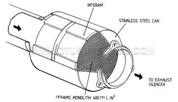
5.2 CATALYST - The catalyst design employed on the Lotus Esprit SE is a split brick design based around a 5.66 inch diameter extruded ceramic substrate.
The bricks have an exceptionally low length to diameter ratio of 0.42 and 0.51 for the front and rear bricks respectively. They are mounted in a stainless steel can using Interam as the constraining and insulation medium following considerable longitudinal and radial substrate expansion testing.
The bricks are mechanically constrained in the longitudinal direction using steel spacers.
The short brick design can be utilised in this application due to the action of the turbine wheel removing the severe exhaust pulse which could otherwise cause premature failure. In addition the relative large face area and CFD/FLIPS modelling of entry and exit conditions ensure that the pressure drop across each brick is kept to a minimum.
The split brick design was established after extensive testing to provide optimum light off characteristics and gas conversion efficiency, allowing differential loadings if required.
The design shows an improvement of light off time over a solid matrix. This is thought to be due to both the lower thermal inertia and heat rejection ability of the first brick, over an equivalent volume of solid brick, and the additional exit/entry turbulence caused by the gap between the bricks.
The coating itself follows conventional three way catalyst practice using nominal metal ratios of 5:1:1. The front and rear substrates carry different loadings to provide suitable light-off and conversion efficiency against precious metal concentration, and hence cost.
5.3 ENGINE MANAGEMENT SYSTEM - The Delco Electronics P4, semi-sequential eight bit microprocessor is used to control the engine management system.
Software is based around that which already existed for another application, but has been specifically developed by Lotus for the unique boost control and back pressure valve systems.
The use of a mass air flow measuring system was considered, but later rejected due to the potential problems of attempting to measure air flow over a linear range with minimum pressure drop from idle to full load flow requirements of 600m°/h. Consequently a speed density system has been utilised.
This offered zero measurement induction pressure restriction, minimum packaging difficulties and potentially better reliability than mass air measurement.
The speed density system proved a difficult challenge to calibrate on an engine using multiple throttles, short induction length, swept volume to downstream throttle ratio of only 0.8 and valve overlap of 42° crank.
The problem was compounded by the turbocharged application since a wide range of manifold air pressure (MAP) measurement is possible at any single throttle angle, and speed, due to the variable boost pressure.
The MAP signal was eventually measured through a series of orifices connecting each induction tract, and filtering the resultant signal both pneumatically and electronically.
Engine to engine and ambient air condition variations are accounted for by the adaptive fuel control system which continuously updates and modifies the basic programmed values.
A barometric sensor is used for altitude compensation, and detonation sensing is used to control the ignition characteristics.
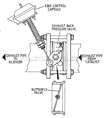
5.4 EXHAUST BACK PRESSURE VALVE (EBPV) - The EBPV comprises a SiMo casting, clamped between the catalyst and silencer, which carries an offset stainless steel throttle plate.
This is sprung shut in the closed position under certain cold start or static conditions using a normal compression spring acting on a lever.
This gives more desirable characteristics than a radial spring and is more easily insulated from radiated exhaust heat.
With the engine running the differential pressures acting on the offset throttle blade self modulates its position with engine load against resistance applied by the compression spring.
This provides an adjustable, and controllable, exhaust back pressure at idle conditions and a gently increasing characteristic as engine load and speed is increased. In this way drivability is not adversely affected to any great extent.
The increase in back pressure during engine warm up has been shown to decrease the measured exhaust emissions. The back pressure has several effects which combine to increase the catalyst's overall performance and reduce exhaust pollutants, these are described.
The back pressure increases engine pumping work, and consequently increases engine load, and hence exhaust gas temperature and mass throughput for the same idle or engine load/speed conditions.
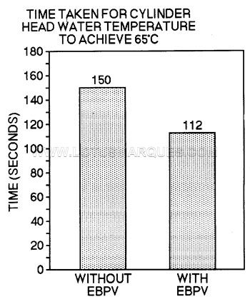
This also has the effect of increased in-cylinder heat rejection to coolant, and is illustrated below showing a comparison of time taken for the cylinder head water temperature to increase from a 25°C ambient start to 65°C during a Federal cold start emission test.
An additional in-cylinder effect is that of creating poor cylinder purging, and hence increasing the proportion of residual exhaust gas remaining causing dilution of the fresh incoming charge.
This is the same effect as an external EGR system.
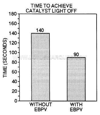
Since the increased back pressure results in a faster rise in exhaust gas temperature than with an ambient pressure, system, the heating effect of the gas on the catalyst will be correspondingly faster with a more rapid increase in catalyst surface temperature, and hence the reaction rate, prior to the catalyst lighting off.
This in turn will lead to a reduced time to catalyst light off as a greater quantity of heat will be generated by the exothermic reactions taking place over the catalyst.
The increased pressure leads to a longer residence time if the gas over the catalyst.
This may increase conversion by reducing any diffusional constraints imposed by the catalyst washcoat porosity. In addition, the longer residence time would lead to improved heat
transfer between the gas phase and the catalyst surface prior to catalyst light-off.
Once a region of the catalyst has reached the temperature where the heat generated by reaction raises the surface temperature above that of the gas phase, ie. the reaction becomes autothermal, the slower gas velocity will remove less heat due to an increased boundary layer effect, despite the thermal capacity of the gas stream being the same as at normal operating pressure.
This enables the exotherm to spread more rapidly across the entire catalyst surface.
The reduction in light-off time is significant and has been shown to reduce the time taken to achieve 50% conversion efficiency, considered light-off, by 35 per cent.
Reduction and oxidation of pollutants could also occur by homogeneous reaction in the gas phase.
These reactions would occur at a significant rate at temperatures in excess of 700°C and the increased residence time in the hot parts of the exhaust system may increase the degree of pollutant conversion by this mechanism.
The subject is a complex one and its mechanism not easily understood or confirmed. However the results achieved, and shown below, as measured during a cold Federal Test bag, can be repeated with high success.
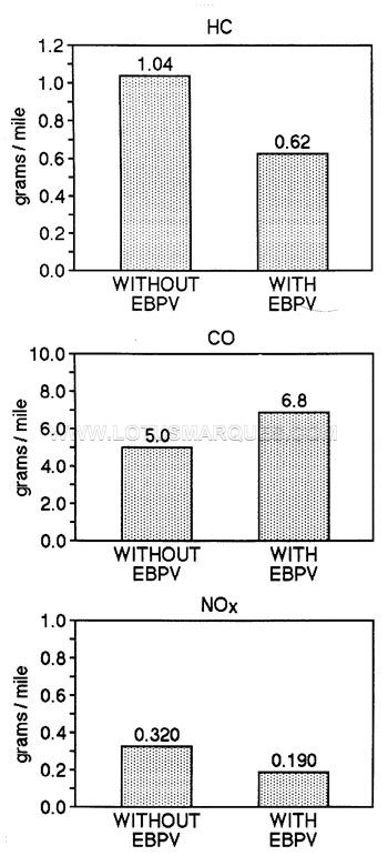
As shown, the negative effect is that CO is increased, which in some applications may cause additional problems. Surprisingly no increase in fuel consumption can be measured although it should be said that the EBPV is only in operation for 120 seconds, or until coolant temperature reaches 65°C.
Once these conditions are met the valve is mechanically opened and then, because of its size, imposes no restriction on the exhaust system.
Continue to Part 3 >
- Lotus 2.2 Lt. Chargecooled Engine
by Simon P. Wood and John H. Bloomfield
Lotus Engineering
Reprinted with permission © 1990 SAE Inc.
5.0 EMISSION CONTROL SYSTEMS
Raw engine out emissions, however low, generally require additional control systems to promote fast catalyst light off and NOx reduction, these are typically air injection and EGR.
The Lotus Esprit SE uses none of these and its only specific raw emission reduction system, other than a catalyst, is a post catalyst exhaust back pressure valve (EBPV).
Principle items to be discussed here include the raw engine out emissions from the combustion chamber, catalyst design, engine management system and the exhaust back pressure valve.
Other areas critical to overall emission performance (multiple throttles, combustion chamber etc) have already been discussed.
5.1 RAW ENGINE OUT EMISSIONS - The data presented below illustrates typical engine out raw emissions from production vehicles over a complete Federal test cycle.
For comparison purposes, to achieve the current legislation targets of 0.41 HC, 3.4 CO and 0.4 NOx gm/mile at 50,000 miles with these raw levels, required catalyst conversion efficiencies of 87%, 79% and 75% respectively. With current technology this is achievable.
Potential future Federal 1994 legislation of 0.32 g/mile HC at 100,000 mile use, will require conversion efficiency of 81%, this suggests that some improvement in raw HC emission scatter will be required.
In the production environment every engine is hot tested, for one hour, and has to achieve the following raw emission targets for each cylinder before being passed to vehicle assembly.
Engine Speed rpm HC(ppm) CO(%)
1000 less than 300 0.8 ± 0.3
2000 less than 300 0.8 ± 0.3
3000 less than 200 0.8 ± 0.3
NOx emission is not checked as this is generally well within emission test audit limits due to the cool combustion chamber design. It is also the exhaust gas least effected by build tolerance or component faults ie, injector leak, valve timing etc.
5.2 CATALYST - The catalyst design employed on the Lotus Esprit SE is a split brick design based around a 5.66 inch diameter extruded ceramic substrate.
The bricks have an exceptionally low length to diameter ratio of 0.42 and 0.51 for the front and rear bricks respectively. They are mounted in a stainless steel can using Interam as the constraining and insulation medium following considerable longitudinal and radial substrate expansion testing.
The bricks are mechanically constrained in the longitudinal direction using steel spacers.
The short brick design can be utilised in this application due to the action of the turbine wheel removing the severe exhaust pulse which could otherwise cause premature failure. In addition the relative large face area and CFD/FLIPS modelling of entry and exit conditions ensure that the pressure drop across each brick is kept to a minimum.
The split brick design was established after extensive testing to provide optimum light off characteristics and gas conversion efficiency, allowing differential loadings if required.
The design shows an improvement of light off time over a solid matrix. This is thought to be due to both the lower thermal inertia and heat rejection ability of the first brick, over an equivalent volume of solid brick, and the additional exit/entry turbulence caused by the gap between the bricks.
The coating itself follows conventional three way catalyst practice using nominal metal ratios of 5:1:1. The front and rear substrates carry different loadings to provide suitable light-off and conversion efficiency against precious metal concentration, and hence cost.
5.3 ENGINE MANAGEMENT SYSTEM - The Delco Electronics P4, semi-sequential eight bit microprocessor is used to control the engine management system.
Software is based around that which already existed for another application, but has been specifically developed by Lotus for the unique boost control and back pressure valve systems.
The use of a mass air flow measuring system was considered, but later rejected due to the potential problems of attempting to measure air flow over a linear range with minimum pressure drop from idle to full load flow requirements of 600m°/h. Consequently a speed density system has been utilised.
This offered zero measurement induction pressure restriction, minimum packaging difficulties and potentially better reliability than mass air measurement.
The speed density system proved a difficult challenge to calibrate on an engine using multiple throttles, short induction length, swept volume to downstream throttle ratio of only 0.8 and valve overlap of 42° crank.
The problem was compounded by the turbocharged application since a wide range of manifold air pressure (MAP) measurement is possible at any single throttle angle, and speed, due to the variable boost pressure.
The MAP signal was eventually measured through a series of orifices connecting each induction tract, and filtering the resultant signal both pneumatically and electronically.
Engine to engine and ambient air condition variations are accounted for by the adaptive fuel control system which continuously updates and modifies the basic programmed values.
A barometric sensor is used for altitude compensation, and detonation sensing is used to control the ignition characteristics.
5.4 EXHAUST BACK PRESSURE VALVE (EBPV) - The EBPV comprises a SiMo casting, clamped between the catalyst and silencer, which carries an offset stainless steel throttle plate.
This is sprung shut in the closed position under certain cold start or static conditions using a normal compression spring acting on a lever.
This gives more desirable characteristics than a radial spring and is more easily insulated from radiated exhaust heat.
With the engine running the differential pressures acting on the offset throttle blade self modulates its position with engine load against resistance applied by the compression spring.
This provides an adjustable, and controllable, exhaust back pressure at idle conditions and a gently increasing characteristic as engine load and speed is increased. In this way drivability is not adversely affected to any great extent.
The increase in back pressure during engine warm up has been shown to decrease the measured exhaust emissions. The back pressure has several effects which combine to increase the catalyst's overall performance and reduce exhaust pollutants, these are described.
The back pressure increases engine pumping work, and consequently increases engine load, and hence exhaust gas temperature and mass throughput for the same idle or engine load/speed conditions.
This also has the effect of increased in-cylinder heat rejection to coolant, and is illustrated below showing a comparison of time taken for the cylinder head water temperature to increase from a 25°C ambient start to 65°C during a Federal cold start emission test.
An additional in-cylinder effect is that of creating poor cylinder purging, and hence increasing the proportion of residual exhaust gas remaining causing dilution of the fresh incoming charge.
This is the same effect as an external EGR system.
Since the increased back pressure results in a faster rise in exhaust gas temperature than with an ambient pressure, system, the heating effect of the gas on the catalyst will be correspondingly faster with a more rapid increase in catalyst surface temperature, and hence the reaction rate, prior to the catalyst lighting off.
This in turn will lead to a reduced time to catalyst light off as a greater quantity of heat will be generated by the exothermic reactions taking place over the catalyst.
The increased pressure leads to a longer residence time if the gas over the catalyst.
This may increase conversion by reducing any diffusional constraints imposed by the catalyst washcoat porosity. In addition, the longer residence time would lead to improved heat
transfer between the gas phase and the catalyst surface prior to catalyst light-off.
Once a region of the catalyst has reached the temperature where the heat generated by reaction raises the surface temperature above that of the gas phase, ie. the reaction becomes autothermal, the slower gas velocity will remove less heat due to an increased boundary layer effect, despite the thermal capacity of the gas stream being the same as at normal operating pressure.
This enables the exotherm to spread more rapidly across the entire catalyst surface.
The reduction in light-off time is significant and has been shown to reduce the time taken to achieve 50% conversion efficiency, considered light-off, by 35 per cent.
Reduction and oxidation of pollutants could also occur by homogeneous reaction in the gas phase.
These reactions would occur at a significant rate at temperatures in excess of 700°C and the increased residence time in the hot parts of the exhaust system may increase the degree of pollutant conversion by this mechanism.
The subject is a complex one and its mechanism not easily understood or confirmed. However the results achieved, and shown below, as measured during a cold Federal Test bag, can be repeated with high success.
As shown, the negative effect is that CO is increased, which in some applications may cause additional problems. Surprisingly no increase in fuel consumption can be measured although it should be said that the EBPV is only in operation for 120 seconds, or until coolant temperature reaches 65°C.
Once these conditions are met the valve is mechanically opened and then, because of its size, imposes no restriction on the exhaust system.
Continue to Part 3 >