
CLEAN POWER -
LOTUS 2.2 Lt. CHARGECOOLED ENGINE
by Simon P. Wood, John H. Bloomfield Lotus Engineering.
Reprinted with permission © 1990 Society of Automotive Engineers, Inc.
I ABSTRACT
For 1989 introduction Lotus further developed its own 2.2 litre four— cylinder turbocharged engine to produce world—leading specific performance of 91 kw/litre (122 bhp/litre), for a production unit. This very high level of performance was achieved in compliance with current proposed Federal and European emissions standards.
2 INTRODUCTION
Over the last decade increasingly stringent worldwide exhaust emission standards have slowed down development of higher specific engine performance.
Lotus have successfully tackled this technical challenge with innovative solutions for its 910 SE 2.2 litre chargecooled engine, associated exhaust emissions control systems and strategy. The engine is mounted in the Lotus Esprit SE, a hyper performance mid engined two seat car, utilising a composite body mounted on a steel back bone chassis.
3 BACKGROUND
The heritage of this engine dates back to the early 1970s, it has been continuously refined and further developed since that time.
Over the production span of the engine considerable changes in emission legislation have occurred up to the present day, where European and Federal legislation for over 2.0 It. engines are broadly similar. This enables production of a single specification power unit for all world markets. The list shown below indicates the principal engine specification changes that have occurred since its initial introduction in 1972. During this period Federal legislation has changed dramatically, this required major revisions, in particular to the exhaust emission control strategy.
Date Performance
1972 104 kw N/A Carburettered
1974 119 kw N/A Carburettered
1980 157 kw Turbo Carburettered
1983 153 kw Turbo Carb + Catalyst
1984 134 kw N/A Carburettered
1985 160 kw Turbo MFI + Catalyst
1987 171 kw Turbo EFI + Catalyst
1989 197 kw Turbo SE EFI + Catalyst
(NB MFI — Mechanical Fuel Injection
EFI — Electronic Fuel Injection)
Legislation : Federal Test Limits (50 State) HC CO NOx
1972 3.4 39.0 2.0
1989 0.41 3.4 0.4 (figures in g/mile)
4 MECHANICAL DESCRIPTION
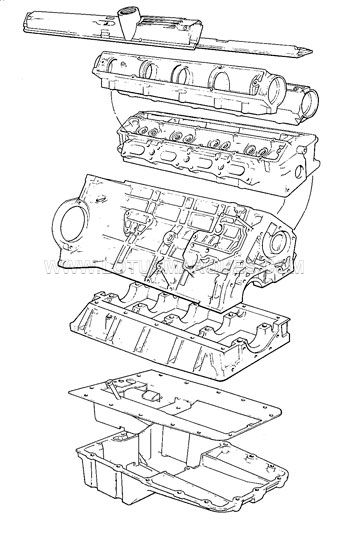
4.1 STRUCTURE — The basic core of the engine is built around a structure of heat treated aluminium alloy castings, the cylinder centreline being inclined at an angle of 45°. The cylinder block is of open deck configuration with free standing Nikasil coated aluminium liners and incorporates a one piece ladder frame connecting all main bearings and a structural sump for maximum stiffness.
The crankshaft is manufactured in SG Iron and runs in copper/ lead bearings. A steel flywheel is used to allow use of minimum inertias whilst maintaining burst strength at maximum engine speed of 7500 rpm.
4.2 PISTON & CYLINDERS — The forged aluminium Nikasil coated liners are bottom spigot located into the block and clamped into position by the cylinder head gasket. Obviously this is a critical joint face having to seal against peak gas pressures of up to 100 bar whilst minimising material distortion of the thin wall liner. Heat transfer properties of the liner are a major contribution to the performance of the engine. They have shown a reduction in the onset of combustion detonation characteristic of some 3° to 5° crank and allow continuous operation running in incipient detonation rather than the catastrophic failure typically experienced using conventional iron liners. During cold start running conditions the heat transfer to coolant is improved, this benefits rates of increase of coolant temperatures and hence heater performance but has also, and more importantly, been shown to increase the level of unburned HC emissions measured over the early stages of the Federal test cycle. Additional HC control systems are, therefore, necessary to achieve legislation demands if the combustion advantages of the aluminium liners are to be utilised.
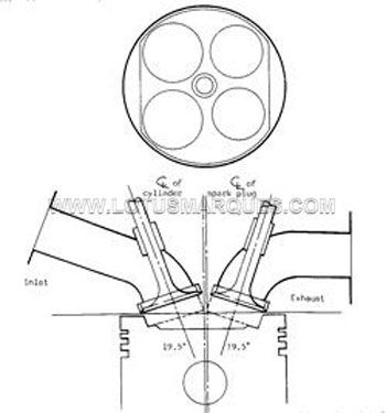
4.3 CYLINDER HEAD & COMBUSTION CHAMBER — The four valve head has a combustion chamber, pentroof in shape, with a central 14 mm sparking plug of twin earth electrode design. This ensures improved earth electrode cooling due to the shorter heat transfer path and has been demonstrated to have greater ability to sustain combustion abuse or slight detonation for longer periods than the conventional single electrode component.
Squish areas are provided at opposite sides of the chamber to increase in cylinder gas movement. A nominal squish clearance of 2 mm has been arrived at through a development exercise considering both detonation limited performance and HC emissions. The squish faces are not parallel in section, but have an included angle of 5 degrees as this was found to give the best compromise.
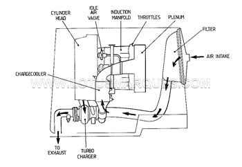
4.4 INDUCTION — The compressor draws clean air via the body mounted filter element. At peak power this imposes a restriction of 55 m.bar at compressor inlet.
Gas from the compressor at temperatures and pressures of up to 150 C and 1.9 bar absolute is cooled by the chargecooler before passing the secondary injectors on entry to the plenum. Multiple throttles (ie one per cylinder) modulate the gas flow to each cylinder. At low throttle openings the `blocking' reflective effect of the individual throttle plates reduce the back pulse from the inlet of one cylinder and hence reduces inlet charge exhaust dilution problems. Traditionally the absence of multiple throttles on engines with relatively long valve overlap periods, in this case 42 degrees crank, can cause HC and feedback fuel flow control problems.
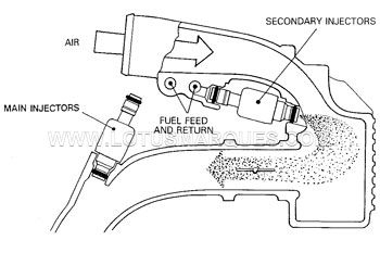
4.5 FUEL SYSTEM — One major problem with very high output per cylinder engines (50 kw/cylinder) is providing injectors that have the required linearity and fuel preparation characteristics at the light load emission range and a full flow requirement of greater than 6.0 gms/sec at full load. AC Rochester are currently working on new designs to fulfil these requirements but at the development stage of the 910 SE engine a 4.3 gm/sec injector was the highest flow available with the required linear control range. This then, required the fuelling strategy to change to four main injectors with additional high load fuel supply via two secondary power injectors.
These main injectors are conventional single spray pencil stream units. Dual cone spray injectors were assessed, however no improvement was determined in idle stability or low speed emissions. It is thought this could be due to the not ideal match of spray and port angles, although some improvement was still expected.
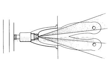
The secondary injectors are placed facing down stream at the entry to the plenum. There use is confined to high load operations only.
Various alternative locations were assessed within the physical constraints of packaging until the final compromise was achieved.
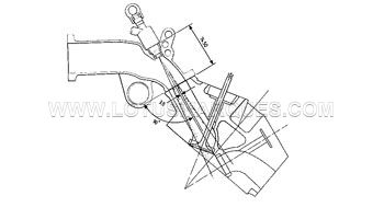
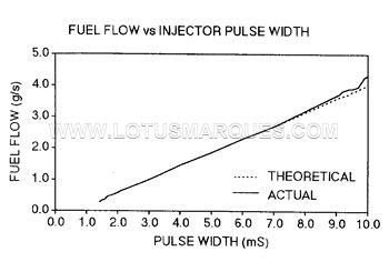
Placing the injectors either further up stream, or facing up stream, although expected to give performance improvements due to improved mixture preparation time and greater latent heat of evaporation, actually reduced performance by about 2%. This was considered due to the weight of air displaced by the additional mass of vapourised fuel and the energy required to overcome the fuel momentum effects. There is little measured difference between the combined use of main and secondary injectors in their final position or the use of single, high flow main injectors only. The latter would obviously be the preferred route, however current technology prevents reliable manufacture of high flow injectors having a linear flow range of greater than about 9:1 or 10:1. The following diagram shows the linear characteristics of the main injectors.
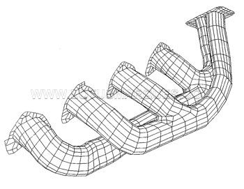
4.6 EXHAUST — The exhaust gas exits through a manifold designed to promote a directed pulse to the turbocharger, which is positioned above the transmission clutch housing. The manifold is manufactured in a high silicon—molybdenum nodular cast iron (SiMo) and is operated at turbine inlet temperatures of up to 980°C. Thermal image techniques have been used to confirm that bulk metal temperatures do not exceed the phase transition temperature of the material which occurs at around 840°C. Considerable CAD effort has been used to determine the final design of the manifold to enable use of SiMo as opposed to NiResist, the former having a lower coefficient of linear expansion which is considered desirable for minimum differential expansion effects.
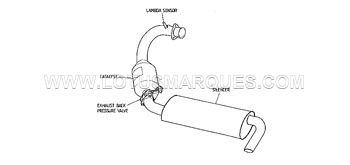
The Garratt AiResearch TBO3 water cooled turbocharger exhausts into a single, diameter 73.5 mm, exhaust system consisting of catalyst, exhaust back pressure valve and single silencer box. The vehicle meets 75 dBA drive-by noise requirements.
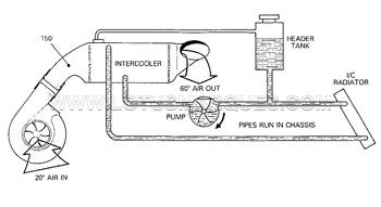
4.7 CHARGECOOLER — The chargecooler is mounted above the engine between the compressor exit and plenum intake. It performs the same function as a conventional turbocharger air/air intercooler except that the cooling fluid is liquid. This system has considerable advantages over an air/air system, especially for mid engine vehicles where packaging and availability of air flow at yaw angles can be a severe constraint.
Fluid is pumped around the system by a positive displacement engine driven pump. This provides a simple and efficient means of variable water flow with increasing heat rejection requirements. The system is sized at maximum vehicle speeds, when operated in a 20 °C ambient, at which air exiting the chargecooler is reduced to 60°C. At lower vehicle speeds the exit temperature is further reduced since heat rejection into the system is also reduced. (NB The vehicle has no trailer towing capability).
The hot coolant, at upto 70°C, exiting the chargecooler is cooled via a tube and fine type radiator at the front of the vehicle. This is, comparatively, a relatively large radiator for the heat rejection needed since the mean temperature difference between the air and coolant is lower than usually used in vehicle cooling systems.
The advantages of this system for the Esprit over an air/air type can be summarised as follows:
— Minimum induction volume for maximum engine response.
— High thermal effectiveness, 69% at peak power.
— Good package, very compact.
— Cooling ability modulated with engine speed.
— High thermal inertia.
— Minimum yaw angle influence.
The high thermal inertia of the system is a direct function of the specific heat capacity of the cooling fluids. In this case the cooling liquid has a Cp of 3.7 against Cp for air of 1.0 kJ/kg"K. Therefore for a similar heat absorption capacity the liquid cooled system can provide an instantaneous cooling ability 3.7 times longer than its equivalent air/air system. This allows higher than certified engine outputs to be achieved for perhaps 30-40 seconds due to the lower charge temperatures. In practice the 30 second installed performance is in the region of 210 kw (280 bhp). It should be remembered that certification performance tests require a stabilized reading to be held for one minute. Obviously this is not representative of dynamic vehicle systems.
Continue to Part 2 >
LOTUS 2.2 Lt. CHARGECOOLED ENGINE
by Simon P. Wood, John H. Bloomfield Lotus Engineering.
Reprinted with permission © 1990 Society of Automotive Engineers, Inc.
I ABSTRACT
For 1989 introduction Lotus further developed its own 2.2 litre four— cylinder turbocharged engine to produce world—leading specific performance of 91 kw/litre (122 bhp/litre), for a production unit. This very high level of performance was achieved in compliance with current proposed Federal and European emissions standards.
2 INTRODUCTION
Over the last decade increasingly stringent worldwide exhaust emission standards have slowed down development of higher specific engine performance.
Lotus have successfully tackled this technical challenge with innovative solutions for its 910 SE 2.2 litre chargecooled engine, associated exhaust emissions control systems and strategy. The engine is mounted in the Lotus Esprit SE, a hyper performance mid engined two seat car, utilising a composite body mounted on a steel back bone chassis.
3 BACKGROUND
The heritage of this engine dates back to the early 1970s, it has been continuously refined and further developed since that time.
Over the production span of the engine considerable changes in emission legislation have occurred up to the present day, where European and Federal legislation for over 2.0 It. engines are broadly similar. This enables production of a single specification power unit for all world markets. The list shown below indicates the principal engine specification changes that have occurred since its initial introduction in 1972. During this period Federal legislation has changed dramatically, this required major revisions, in particular to the exhaust emission control strategy.
Date Performance
1972 104 kw N/A Carburettered
1974 119 kw N/A Carburettered
1980 157 kw Turbo Carburettered
1983 153 kw Turbo Carb + Catalyst
1984 134 kw N/A Carburettered
1985 160 kw Turbo MFI + Catalyst
1987 171 kw Turbo EFI + Catalyst
1989 197 kw Turbo SE EFI + Catalyst
(NB MFI — Mechanical Fuel Injection
EFI — Electronic Fuel Injection)
Legislation : Federal Test Limits (50 State) HC CO NOx
1972 3.4 39.0 2.0
1989 0.41 3.4 0.4 (figures in g/mile)
4 MECHANICAL DESCRIPTION
4.1 STRUCTURE — The basic core of the engine is built around a structure of heat treated aluminium alloy castings, the cylinder centreline being inclined at an angle of 45°. The cylinder block is of open deck configuration with free standing Nikasil coated aluminium liners and incorporates a one piece ladder frame connecting all main bearings and a structural sump for maximum stiffness.
The crankshaft is manufactured in SG Iron and runs in copper/ lead bearings. A steel flywheel is used to allow use of minimum inertias whilst maintaining burst strength at maximum engine speed of 7500 rpm.
4.2 PISTON & CYLINDERS — The forged aluminium Nikasil coated liners are bottom spigot located into the block and clamped into position by the cylinder head gasket. Obviously this is a critical joint face having to seal against peak gas pressures of up to 100 bar whilst minimising material distortion of the thin wall liner. Heat transfer properties of the liner are a major contribution to the performance of the engine. They have shown a reduction in the onset of combustion detonation characteristic of some 3° to 5° crank and allow continuous operation running in incipient detonation rather than the catastrophic failure typically experienced using conventional iron liners. During cold start running conditions the heat transfer to coolant is improved, this benefits rates of increase of coolant temperatures and hence heater performance but has also, and more importantly, been shown to increase the level of unburned HC emissions measured over the early stages of the Federal test cycle. Additional HC control systems are, therefore, necessary to achieve legislation demands if the combustion advantages of the aluminium liners are to be utilised.
4.3 CYLINDER HEAD & COMBUSTION CHAMBER — The four valve head has a combustion chamber, pentroof in shape, with a central 14 mm sparking plug of twin earth electrode design. This ensures improved earth electrode cooling due to the shorter heat transfer path and has been demonstrated to have greater ability to sustain combustion abuse or slight detonation for longer periods than the conventional single electrode component.
Squish areas are provided at opposite sides of the chamber to increase in cylinder gas movement. A nominal squish clearance of 2 mm has been arrived at through a development exercise considering both detonation limited performance and HC emissions. The squish faces are not parallel in section, but have an included angle of 5 degrees as this was found to give the best compromise.
4.4 INDUCTION — The compressor draws clean air via the body mounted filter element. At peak power this imposes a restriction of 55 m.bar at compressor inlet.
Gas from the compressor at temperatures and pressures of up to 150 C and 1.9 bar absolute is cooled by the chargecooler before passing the secondary injectors on entry to the plenum. Multiple throttles (ie one per cylinder) modulate the gas flow to each cylinder. At low throttle openings the `blocking' reflective effect of the individual throttle plates reduce the back pulse from the inlet of one cylinder and hence reduces inlet charge exhaust dilution problems. Traditionally the absence of multiple throttles on engines with relatively long valve overlap periods, in this case 42 degrees crank, can cause HC and feedback fuel flow control problems.
4.5 FUEL SYSTEM — One major problem with very high output per cylinder engines (50 kw/cylinder) is providing injectors that have the required linearity and fuel preparation characteristics at the light load emission range and a full flow requirement of greater than 6.0 gms/sec at full load. AC Rochester are currently working on new designs to fulfil these requirements but at the development stage of the 910 SE engine a 4.3 gm/sec injector was the highest flow available with the required linear control range. This then, required the fuelling strategy to change to four main injectors with additional high load fuel supply via two secondary power injectors.
These main injectors are conventional single spray pencil stream units. Dual cone spray injectors were assessed, however no improvement was determined in idle stability or low speed emissions. It is thought this could be due to the not ideal match of spray and port angles, although some improvement was still expected.
The secondary injectors are placed facing down stream at the entry to the plenum. There use is confined to high load operations only.
Various alternative locations were assessed within the physical constraints of packaging until the final compromise was achieved.
Placing the injectors either further up stream, or facing up stream, although expected to give performance improvements due to improved mixture preparation time and greater latent heat of evaporation, actually reduced performance by about 2%. This was considered due to the weight of air displaced by the additional mass of vapourised fuel and the energy required to overcome the fuel momentum effects. There is little measured difference between the combined use of main and secondary injectors in their final position or the use of single, high flow main injectors only. The latter would obviously be the preferred route, however current technology prevents reliable manufacture of high flow injectors having a linear flow range of greater than about 9:1 or 10:1. The following diagram shows the linear characteristics of the main injectors.
4.6 EXHAUST — The exhaust gas exits through a manifold designed to promote a directed pulse to the turbocharger, which is positioned above the transmission clutch housing. The manifold is manufactured in a high silicon—molybdenum nodular cast iron (SiMo) and is operated at turbine inlet temperatures of up to 980°C. Thermal image techniques have been used to confirm that bulk metal temperatures do not exceed the phase transition temperature of the material which occurs at around 840°C. Considerable CAD effort has been used to determine the final design of the manifold to enable use of SiMo as opposed to NiResist, the former having a lower coefficient of linear expansion which is considered desirable for minimum differential expansion effects.
The Garratt AiResearch TBO3 water cooled turbocharger exhausts into a single, diameter 73.5 mm, exhaust system consisting of catalyst, exhaust back pressure valve and single silencer box. The vehicle meets 75 dBA drive-by noise requirements.
4.7 CHARGECOOLER — The chargecooler is mounted above the engine between the compressor exit and plenum intake. It performs the same function as a conventional turbocharger air/air intercooler except that the cooling fluid is liquid. This system has considerable advantages over an air/air system, especially for mid engine vehicles where packaging and availability of air flow at yaw angles can be a severe constraint.
Fluid is pumped around the system by a positive displacement engine driven pump. This provides a simple and efficient means of variable water flow with increasing heat rejection requirements. The system is sized at maximum vehicle speeds, when operated in a 20 °C ambient, at which air exiting the chargecooler is reduced to 60°C. At lower vehicle speeds the exit temperature is further reduced since heat rejection into the system is also reduced. (NB The vehicle has no trailer towing capability).
The hot coolant, at upto 70°C, exiting the chargecooler is cooled via a tube and fine type radiator at the front of the vehicle. This is, comparatively, a relatively large radiator for the heat rejection needed since the mean temperature difference between the air and coolant is lower than usually used in vehicle cooling systems.
The advantages of this system for the Esprit over an air/air type can be summarised as follows:
— Minimum induction volume for maximum engine response.
— High thermal effectiveness, 69% at peak power.
— Good package, very compact.
— Cooling ability modulated with engine speed.
— High thermal inertia.
— Minimum yaw angle influence.
The high thermal inertia of the system is a direct function of the specific heat capacity of the cooling fluids. In this case the cooling liquid has a Cp of 3.7 against Cp for air of 1.0 kJ/kg"K. Therefore for a similar heat absorption capacity the liquid cooled system can provide an instantaneous cooling ability 3.7 times longer than its equivalent air/air system. This allows higher than certified engine outputs to be achieved for perhaps 30-40 seconds due to the lower charge temperatures. In practice the 30 second installed performance is in the region of 210 kw (280 bhp). It should be remembered that certification performance tests require a stabilized reading to be held for one minute. Obviously this is not representative of dynamic vehicle systems.
Continue to Part 2 >