
This problem is usually brought about by rear of the car being raised from the ground (to gain access to the drive shaft components, fastening bolts etc.) and the suspension being at full droop.
This presents a situation where the Rotoflex couplings are being stretched and distorted to their maximum design limits.
Trying to manipulate the various components in this position and install the coupling bolts is almost impossible.
The usual response to this is to try and raise the road wheel to compress the spring, in an attempt to reduce the suspension droop.
This eventually results in the entire car being lifted off the ground without compressing the road spring to a suitable position where the coupling bolts may be easily installed.
The above scenario is far from desirable, as the car is usually not supported safely to allow the operator to move under the vehicle to install the coupling bolts.
So, how can this task be carried out quickly and efficiently?
Analysing the problem makes you realise that the bolts ideally need to be installed at a point where the couplings experience minimal distortion.
This point is where the outboard drive shaft is on the same axis as the differential output drive shaft and the intermediate drive shaft is parallel to the ground.
Therefore the road spring needs to be compressed sufficiently to allow the outboard drive shaft to be moved upwards to the point where it is in alignment with the differential drive shaft.
This can be easily carried out with the aid of a small threaded coil spring compressor.
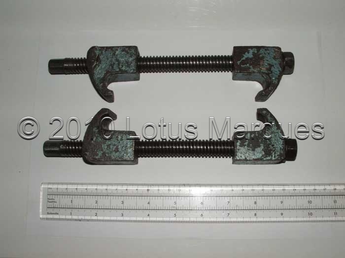
From experience it is advisable to use a small spring compressor that is approximately 9.5 inches long and has a spring compressed height of approximately 3.0 inches.
If a longer compressor is used then the threaded rods are going to foul on the spring perches or other components
The coil spring compressor (threaded rod and hook construction) should be installed in the middle of the road spring across 5 to 6 coils and at 180 degrees apart.
The compressor should be gradually tightened to the point where the enclosed coils touch each other and become solid.
Compressing the road spring in this manner allows the outboard drive shaft and wheel bearing housing to be moved up and down freely in the vertical plane.
Due consideration also needs to be given to the variation in drive shaft components and how this impacts on the reassembly procedure.
During production, later cars were fitted with a “fail–safe” modification to the drive shafts.
This modification comprised of welding 10mm diameter pegs that protrude 32mm from the centre of the three-finger drive flange, on both outboard and differential drive shafts.
The intermediate drive shafts were also modified by welding tubes that protrude from the centre of the three-finger drive flange at both ends of the shaft.
Once assembled, the pegs are located inside the tubes without contacting each other during normal use.
In the unlikely event of a rubber drive shaft-coupling breaking, the “fail–safe” modification prevents the intermediate shaft from uncontrollably thrashing around and damaging the body, chassis, suspension components etc.
The above modification appears to be logical and sensible, but in fact makes reassembly of the rear drive shafts and Rotoflex couplings more difficult.
The addition of the pins and tubes effectively makes the shafts longer.
During reassembly, the tubes present a step for the pins to negotiate before being located inside.
This means the overall axle length is effectively increased during the assembly process.
Therefore some additional space or movement has to be found within the suspension components until the pins are located inside the retaining tubes.
This can only be achieved by disconnecting the lower rear suspension “A” frame from the alloy wheel bearing housing.
To safely and quickly carry out the replacement of rubber drive shaft couplings, the following procedure is recommended.
Reassembly Procedure
It is assumed that new Rotoflex couplings are being installed and have been supplied in the compressed or “banded state”.
If the old or original couplings are being reinstalled, then the couplings will need to be compressed with the aid of hose clamps.
It is recommended that this procedure be carried out on a level concrete floor for safety reasons.
The vehicle should be raised and supported by two axle stands suitably placed at the rear so as not to damage the chassis or interfere with the suspension components.
Assuming the vehicle has been raised on axle stands and the various drive train components including rear wheels have previously been removed, and then follow the instructions below.
1. Ensure the hand brake is off and the gearbox selector/lever is in neutral.
2. Bolt a Rotoflex coupling to one end of intermediate drive shaft
3. Ensure the Rotoflex couplings are orientated correctly when bolting to drive shafts.
The extended part of the metal boss that protrudes from one side the rubber coupling should be in contact with the face of the metal drive shaft flange.
4. Bolt the next rotoflex coupling to the other end of the intermediate drive shaft.
5. During assembly it is recommended that anti-seize compound be applied to all 7/16 UNF drive shaft bolt shanks ONLY.
This will assist removal of bolts at a later date.
6. Bolt rotoflex coupling (complete with intermediate shaft) to brake disc and outboard drive shaft.
7. Detach bottom of suspension leg from rear suspension “A” frame.
8. Compress road spring with suitable spring compressor as described previously.
9. Raise the alloy rear wheel bearing hub, complete with couplings and intermediate drive shaft until the differential drive shaft peg locates in the end of the intermediate drive shaft.
10. Bolt the innermost Rotoflex coupling to differential drive shaft.
11. Insert bolts at 6 ‘O’ Clock for easy assembly and rotate differential drive shaft to next bolt location.
12. Ensure bolts are orientated correctly when securing rotoflex couplings to drive shafts.
13. Fit new 7/16 UNF nyloc nuts and tighten to recommended torque settings.
14. Fit bottom of suspension leg to rear suspension “A” frame
15. Remove the spring compressor from road spring.
Copyright © 2011 Lotus Marques
Yes, we sell rotoflex couplings! Please contact us for price and availability.