The CAS Hall effect sensor assembly, Lotus part number Al00E6020H is now obsolete and part number A1OOE0102S should be used to effect repairs.
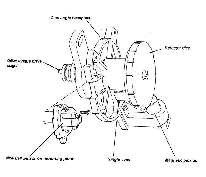
The cam angle sensor assembly on M100 Elan Turbo models is mounted on the left hand end of the cylinder head. This consists of a baseplate and insulated cover containing two electronic sensors; a variable reluctance magnetic pick up and reluctor disc. These components are used by the ECM to measure engine speed and control ignition timing. A Hall effect sensor and single rotary vane, provides a timing reference ('sync pulse') for the injection sequence.
If an engine management fault code 41 is observed, this indicates a fault with the cam angle sensor assembly, and the first item to be checked is the cam belt tension (Service Notes sub-section EC.4) This should be corrected if necessary, as a slightly slack belt can cause sufficient flutter to upset the sensor tolerances. If further diagnosis of code 41 indicates that the cam angle sensor should be replaced, it is likely that the Hall sensor is the faulty component. A new type of hall sensor is now available, which may be fitted to the cam angle sensor base-plate using an adaptor plinth.
Parts Required
Hall Effect Sensor A1OOE0102S 1 off (replaces A100E6569S/R)
Fitting Procedure
Although the Hall sensor can be replaced without removing the cam angle sensor assembly from the engine, the adjustment of the sensor to vane clearance is best achieved with the assembly on the bench.
1. Use the Tech 1 diagnostic tool to clear any fault codes.
2. Mark the position of the cam angle sensor base-plate against the cylinder head, unplug the harness connector from both sensors, Release the single base-plate clamp screw, and withdraw the assembly from the engine.
3. Remove the cover, and release the two screws (5.5 mm socket) securing the Hall effect sensor.
4. Fit the new sensor complete with its adaptor plinth to the cam angle baseplate using the original hall sensor retaining screws. Position the single rotary vane between the jaws of the new sensor, and adjust the sensor position to set the vane midway between the two jaws. Refit the cover.
5. Cut the old Hall effect sensor connector off the engine harness, close to the connector. Strip the cable ends, feed on the cable seals, and crimp the three new terminals onto the cables. Insert the terminals into the new block connector in the positions shown in the illustration, and fit the yellow keeper...
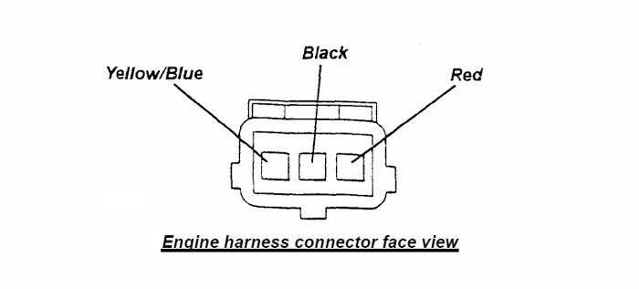
Check that the cable colour match:
( Green ..............................Yellow/Blue )
Hall sensor flying lead ( Black ...............................Black ) Engine harness connector
( Red .................................Red )
Refit the cam angle sensor assembly to the engine, engaging the offset tongue and slot mechanism, and retain the baseplate with the single clamp screw and washer. Align the match marks made on dis-assembly before tightening the clamp screw to 24 Nm. Check the base ignition timing (16° BTDC) as detailed in Service Notes sub-section EMK.3 - N (non catalyst) or EMJ.3 - N (catalyst) noting that this can only be checked in field service mode. Follow this procedure fully and carefully.
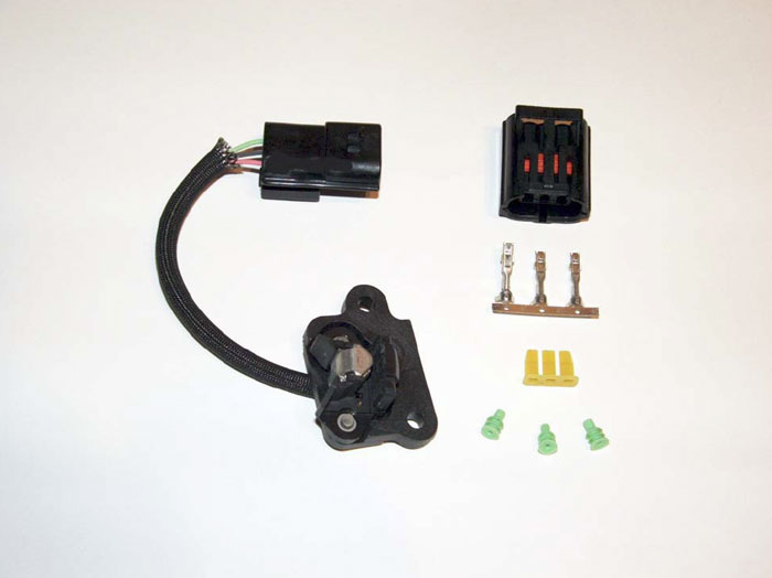
Contents of Hall effect sensor kit A1OOE1020S