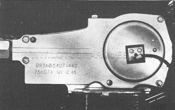
Windscreen wiper motor technical specifications
Manufacturer Lucas
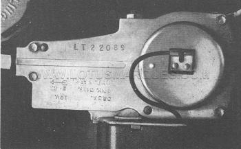
Type DR3A
Lucas part No.
R.H. Steer 54071439
L.H. Steer 54071440
Stanpart No.
R.H. Steer 212793
L.H. Steer 212794
Running current—after 60 seconds from cold with connecting rod removed: At normal speed running current is 3.4 Amps. max.
At high speed the running current is 2.6 Amps. max.
Running speed—Final gear after 60 seconds from cold with connecting rod removed:
Normal speed 44 - 48 r.p.m.
High speed 58 - 68 r.p.m.
Field winding resistance 8.0-9.5 ohms at 15.5 degrees Centigrade
High speed field resistor 9.5 - 11.0 ohms
Brush force against commutator—new 4.4 - 5.6 ozs.
Maximum permissible force to move cable rack in tubing — arms and blades removed 6.0 lbs
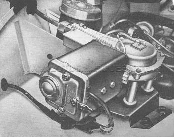 Lotus Elan S1, S2 windscreen wiper motor general layout
Description
The windscreen wiper motor comprises a two speed electric motor and a gearbox unit which drives a cable rack mechanism.
Rotation of the motor armature is converted to a reciprocating motion of the cable rack by a single stage worm and gear, a connecting rod and a cross-head contained in a guide channel.
A switching feature stops the arms and blades in the park position irrespective of their position when the facia switch is selected OFF.
This is effected by a limit switch contained in the gearbox.
The limit switch components are a moving contact mounted on the crank pin and a sector type fixed contact in the domed cover.
For the greater part of each stroke the limit switch contacts are closed providing an earth return for the motor current parallel to the facia switch.
When the facia switch is selected OFF the motor will continue to run until the limit switch contacts open which will occur when the arms and blades are in the park position.
The park position can be adjusted by rotation of the domed cover which positions the sector type fixed contact.
Service
The windscreen wiper motor is greased during manufacture and no maintenance is required.
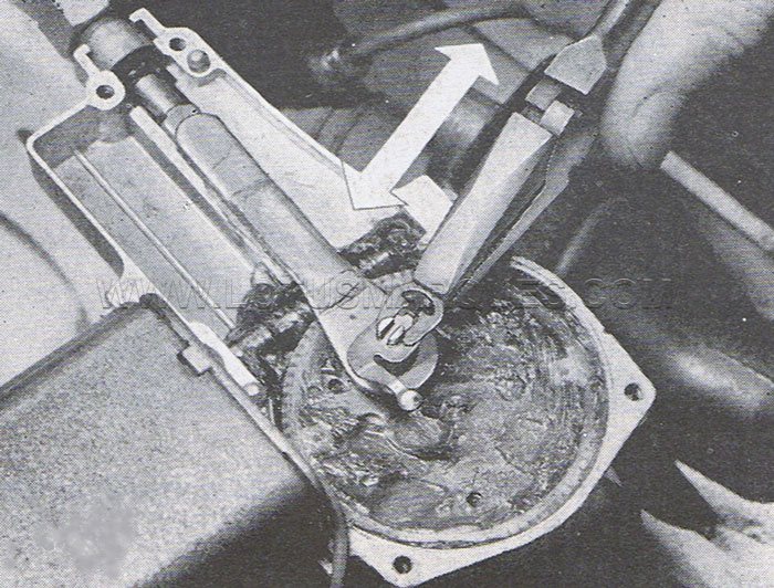
 Crank pin spring clip being removed
Remove Windscreen Wiper Motor
1. Disconnect electrical connections.
2. Remove connecting rod as detailed below.
3. Remove mounting bracket from bulkhead.
4. Manoeuvre unit to allow cross-head and tubing assembly to be released.
5. Remove mounting bracket.
Install Windscreen Wiper Motor
1. Fit mounting bracket to windscreen wiper motor.
2. Position unit so cross-head and tubing assembly are correctly located in guide channel.
3. Fit mounting bracket to bulkhead. Ensure to secure harness earth wire under rearmost bolt. Ensure good electrical contact.
4. Install connecting rod as detailed below.
5. Connect electrical connections and secure wires under adjacent clip.
6. Wet windscreen and perform functional test. Ensure park position is correct. If adjustment is required adjust as detailed below.
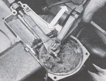
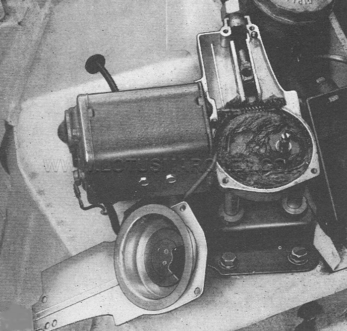
 Connecting rod removed
Remove Connecting Rod
1. Mark position of domed cover with relation to gearbox cover. This will facilitate connecting rod installation.
2. Remove four screws. Swing gearbox cover and domed cover clear.
3. Remove crank pin spring clip by withdrawing connecting rod removed sideways as shown previously.
4. Remove limit switch moving contact.
5. Remove connecting rod.
Install Connecting Rod
1. Fit connecting rod.
2. Fit limit switch moving contact.
3. Fit crank pin spring clip by inserting side-ways as shown previously above.
4. Position gearbox cover and domed cover with marks made above aligned. Secure with four screws.
If aligning marks have been lost adjust park position as detailed below.
Adjust Park Position
The arms and blades should stop at the end of a stroke.
The park position can be adjusted by slackening four screws and rotating the domed cover.
 Park position—R.H. Steer cover.
The correct park position should be attained when the domed cover setting pip is positioned as shown on for R.H. Steer and L.H. Steer vehicles respectively.
 Park position-L.H. Steer
To retard stop rotate domed cover clockwise.
To advance stop rotate domed cover anti-clockwise.
When the domed cover is positioned correctly tighten four screws.
Repair
If the windscreen wiper motor is not operating correctly perform the voltage check as detailed below to locate the fault.
Windscreen motor component and wiring diagram
1. Supply
2. Armature
3. Field winding
4. High speed field resistor
5. Limit switch
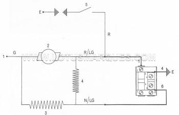 Windscreen wiper motor and switch schematic
Colour code
G = Green
R = Red
N = Brown
LG = Light green
Facia switch
OFF 1 connected to 6
NORMAL 1 and 6 connected to 4
HIGH 1 connected to 4
Voltage Check
1. Connect voltmeter suitable for voltage between supply wire (Colour code—Green) and earth.
2. Select motor ON. Voltmeter reading should be approximately 11.5 volts.
If the reading is zero check supply circuit. If the reading is appreciably below 11.5 volts excessive current flow through the motor is indicated.
This may be due to a fault in the motor or a fault in the cable rack and tubing assembly resulting in the motor being required to drive an excessive load.
Running Current
1. Remove connecting rod as detailed above.
2. Connect ammeter suitable for running current (see technical specifications) in supply circuit.
3. Select motor ON. Allow to run for 60 seconds.
Ammeter reading should then be as given in the specifications.
If the reading is not as stated a fault in the motor is indicated.
Running Speed
1. Remove connecting rod as detailed above.
2. Select motor ON. Allow to run for 60 seconds. Speed of final gear should then be as given in the specifications.
If the speed is not as stated a fault in the motor is indicated.
Force to move Cable Rack in Tubing
1. Remove connecting rod as detailed above.
2. Remove arms and blades.
3. Attach a suitable spring scale to hole in cross-head.
Maximum permissible force to move cable rack in tubing is given in the specifications.
If the required force is greater than stated a fault in the cable rack and tubing assembly is indicated.
Manufacturer Lucas
Type DR3A
Lucas part No.
R.H. Steer 54071439
L.H. Steer 54071440
Stanpart No.
R.H. Steer 212793
L.H. Steer 212794
Running current—after 60 seconds from cold with connecting rod removed: At normal speed running current is 3.4 Amps. max.
At high speed the running current is 2.6 Amps. max.
Running speed—Final gear after 60 seconds from cold with connecting rod removed:
Normal speed 44 - 48 r.p.m.
High speed 58 - 68 r.p.m.
Field winding resistance 8.0-9.5 ohms at 15.5 degrees Centigrade
High speed field resistor 9.5 - 11.0 ohms
Brush force against commutator—new 4.4 - 5.6 ozs.
Maximum permissible force to move cable rack in tubing — arms and blades removed 6.0 lbs
 Lotus Elan S1, S2 windscreen wiper motor general layout
Description
The windscreen wiper motor comprises a two speed electric motor and a gearbox unit which drives a cable rack mechanism.
Rotation of the motor armature is converted to a reciprocating motion of the cable rack by a single stage worm and gear, a connecting rod and a cross-head contained in a guide channel.
A switching feature stops the arms and blades in the park position irrespective of their position when the facia switch is selected OFF.
This is effected by a limit switch contained in the gearbox.
The limit switch components are a moving contact mounted on the crank pin and a sector type fixed contact in the domed cover.
For the greater part of each stroke the limit switch contacts are closed providing an earth return for the motor current parallel to the facia switch.
When the facia switch is selected OFF the motor will continue to run until the limit switch contacts open which will occur when the arms and blades are in the park position.
The park position can be adjusted by rotation of the domed cover which positions the sector type fixed contact.
Service
The windscreen wiper motor is greased during manufacture and no maintenance is required.
 Crank pin spring clip being removed
Remove Windscreen Wiper Motor
1. Disconnect electrical connections.
2. Remove connecting rod as detailed below.
3. Remove mounting bracket from bulkhead.
4. Manoeuvre unit to allow cross-head and tubing assembly to be released.
5. Remove mounting bracket.
Install Windscreen Wiper Motor
1. Fit mounting bracket to windscreen wiper motor.
2. Position unit so cross-head and tubing assembly are correctly located in guide channel.
3. Fit mounting bracket to bulkhead. Ensure to secure harness earth wire under rearmost bolt. Ensure good electrical contact.
4. Install connecting rod as detailed below.
5. Connect electrical connections and secure wires under adjacent clip.
6. Wet windscreen and perform functional test. Ensure park position is correct. If adjustment is required adjust as detailed below.
 Connecting rod removed
Remove Connecting Rod
1. Mark position of domed cover with relation to gearbox cover. This will facilitate connecting rod installation.
2. Remove four screws. Swing gearbox cover and domed cover clear.
3. Remove crank pin spring clip by withdrawing connecting rod removed sideways as shown previously.
4. Remove limit switch moving contact.
5. Remove connecting rod.
Install Connecting Rod
1. Fit connecting rod.
2. Fit limit switch moving contact.
3. Fit crank pin spring clip by inserting side-ways as shown previously above.
4. Position gearbox cover and domed cover with marks made above aligned. Secure with four screws.
If aligning marks have been lost adjust park position as detailed below.
Adjust Park Position
The arms and blades should stop at the end of a stroke.
The park position can be adjusted by slackening four screws and rotating the domed cover.
 Park position—R.H. Steer cover.
 The correct park position should be attained when the domed cover setting pip is positioned as shown on for R.H. Steer and L.H. Steer vehicles respectively.
 Park position-L.H. Steer
To retard stop rotate domed cover clockwise.
To advance stop rotate domed cover anti-clockwise.
When the domed cover is positioned correctly tighten four screws.
Repair
If the windscreen wiper motor is not operating correctly perform the voltage check as detailed below to locate the fault.
Windscreen motor component and wiring diagram
1. Supply
2. Armature
3. Field winding
4. High speed field resistor
5. Limit switch
 Windscreen wiper motor and switch schematic
 Colour code
G = Green
R = Red
N = Brown
LG = Light green
Facia switch
OFF 1 connected to 6
NORMAL 1 and 6 connected to 4
HIGH 1 connected to 4
Voltage Check
1. Connect voltmeter suitable for voltage between supply wire (Colour code—Green) and earth.
2. Select motor ON. Voltmeter reading should be approximately 11.5 volts.
If the reading is zero check supply circuit. If the reading is appreciably below 11.5 volts excessive current flow through the motor is indicated.
This may be due to a fault in the motor or a fault in the cable rack and tubing assembly resulting in the motor being required to drive an excessive load.
Running Current
1. Remove connecting rod as detailed above.
2. Connect ammeter suitable for running current (see technical specifications) in supply circuit.
3. Select motor ON. Allow to run for 60 seconds.
Ammeter reading should then be as given in the specifications.
If the reading is not as stated a fault in the motor is indicated.
Running Speed
1. Remove connecting rod as detailed above.
2. Select motor ON. Allow to run for 60 seconds. Speed of final gear should then be as given in the specifications.
If the speed is not as stated a fault in the motor is indicated.
Force to move Cable Rack in Tubing
1. Remove connecting rod as detailed above.
2. Remove arms and blades.
3. Attach a suitable spring scale to hole in cross-head.
Maximum permissible force to move cable rack in tubing is given in the specifications.
If the required force is greater than stated a fault in the cable rack and tubing assembly is indicated.